


 Related Products - Click to open in new window File Links - Click links to download documentation Inductive Switch Options Switch Functions & Definitions Wiring Instructions | Pressure Gauge With Inductive Contacts - 100mm & 160mm (ATEX Option)
Pressure gauges can be supplied with three
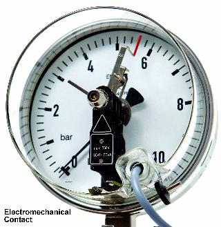
types of electric alarm contacts: Inductive (Non-Contact) which this data sheet
relates to, Electromechanical (Sliding design or Magnetic Snap Action design)
and Electronic (Non-Contact).
General
Information - Inductive Contacts
Inductive contacts have non-contact electric
displacement pickups according to EN 60947-5-6 or NAMUR
The inductive contact consists of 3 main
components:
The gauge indicating pointer can freely move
beyond the selected set point of the electrical contact which remains active
allowing accurate measurement still to be made to the full scale of the
instrument.
A contact adjustment lock allows the user to
adjust the setting pointer to the value at which the unit has to switch.
Inductive
Contact – Principle of Operation
Inductive contacts are used in connection
with a switching amplifier which supplies the control head with direct voltage.
As the control flag mounted on the instrument indicating pointer reaches
thecontrol head the internal resistance in the control head increases. This
causes the current to change and is used to control the switching amplifier.
The amplifier converts the input signal into a binary output signal.
Due to the non-contacting switching function
this design of switch offers high switching accuracy and long service life .This
design is particularly recommended for applications with a high switching
frequency or where high reliability is required. Assuming a suitable isolating
switching amplifier is used, this instrument can be used on intrinsically safe
applications.
ATEX
Option: If a suitable isolating
amplifier is used (such as our model KFA6-SR2-Ex) the system will confirm to
the following Intrinsically Safe Hazardous Classification and maybe used in
hazardous area Zone 1 and 2. Please note however that the isolating switching
amplifier must always be installed in the safe area (outside the hazardous
area): Ex II 2G EEx ia IIC T6 or Ex II 1G EEx ia IIC T6
|